We love the way friction gives us traction on the road, good brakes, and allows us to walk without looking like a newborn Bambi, but there are also things we can’t stand about it—engines seizing up, stuck bolts, and old grandfather clocks never chiming again. We absolutely need friction, and sometimes we absolutely need less of it, but what’s most important is we need to design for it to be consistent. When we’re dealing with gears, we want parts sliding over each other like eager puppies, but in the same assembly we may need two parts move smoothly, as only comes from controlled friction. How do you control the friction in your assembly of moving parts?
Friction basics
Before we try to control friction, we need to understand it. Friction results from two bodies interacting at their contact surface, is always trying to resist movement between the two bodies, and comes in two basic flavors: static and kinetic.
The maximum friction for either case is
μFn
where μ is a constant proportional to the “stickiness” of the two bodies, dependent on materials and surface finishes (for instance, it’s very high between rubber and rough concrete, but very low between steel and teflon), and
Fn
is the normal force—the amount of force pushing the two bodies closer together. Pretty simple, except that the friction constant is different for situations in which the bodies are moving, versus when they’re stationary against each other.
If you’ve ever been pushing really hard against a box, only to have it suddenly lurch forward leaving you flat on the ground, you’ve done an intuitive—albeit painful—experiment to prove this. As long as two parts are stuck against each other, their coefficient of friction
μstatic , often abbreviated μs
is higher than when the parts are moving against each other (as long as you stay above the atomic level—we engineers tend to be practical folk).

Static friction is essential for traction and is what keeps us from sliding around when we’re walking. As long as the two bodies aren’t moving against each other, even when a force is applied, then the formula for the friction looks like this:
Ff μsFn
Once the force trying to slide the parts against each other becomes greater than the
Fstatic-friction-max
the parts will begin to slide—but not smoothly: Because the kinetic friction is less than static, the moving body will suddenly accelerate.
The kinetic friction equation looks very similar to static:
Ff = μkFn
but with that lower coefficient of friction
(μk<μs)
is less. For most scenarios, you won’t want to deal with the transition between these two, because of the sudden lurching when kinetic friction becomes dominant. Unfortunately, one of the worst design issues is “stick-slip”, in which a mechanism alternates between the two friction states.
Stick-Slip Scenarios
Stick-slip is fairly easy to understand but can have dire consequences. For an easy example, let’s look at a car trying to stop in the wintertime. You’re driving along on dry pavement, not too fast, and see that an intersection is coming up. You apply the brakes. In the brake system, the brake pads are gripping the discs with kinetic friction, allowing the discs to slide by in a controlled way. The tires are gripping the pavement with static friction, also giving you control and traction. It’s all good.
Now you hit a patch of ice, and your old Jeep doesn’t have anti-lock brakes. Suddenly the brakes lock up, moving from kinetic to static friction, while the tires do the opposite, completely losing traction on the road, and moving to lower-resistance kinetic friction. You release the brakes, trying to restore the static friction of the tires to the road. And as long as the ice is relatively uniform, you’ll probably be fine.

However, if you suddenly hit a patch of dry pavement while you’re sliding sideways along the icy road, you’re in for some trouble: the sudden sticking of the sliding tires is likely to flip your car. Another, less dangerous/fun (growing up in Colorado you learn to play on icy roads as a teenager; don’t tell my parents) example of stick slip is when you’re trying to close an old dresser drawer, and it keeps torqueing side to side, sliding one painstaking inch at a time. So, whether dangerous or merely annoying, how do you avoid stick-slip scenarios? Geometry, my dear Watson.
Avoiding Stick-Slip Scenarios
The easiest way to avoid the dreaded stick-slip is to design your geometry to avoid situations with quickly fluctuating forces, which often happens from over-constraint or misalignment.
In the example of the old dresser drawer, this happens because the length of the drawer is too short compared to the gaps in the width, so the drawer gets crooked and jams against the side. This commonly happens in many linear motion scenarios, and the solution is easy: Make linear guides as long as possible to avoid jamming.
Another common design scenario is when a machine part is guided along two parallel rails. At first glance, this seems like a great design: The two rails ensure alignment, and with some decent bushings, the moving part should glide along easily. Right? Wrong.

Let’s look at the degrees of freedom (DOFs). The first rail will allow movement in the z direction, restricting movement in x and y. It also allows rotation about the z axis, while restricting rotation about the x and y axes. The first rail eliminates four DOFs, allowing movement in two—and our goal is to have movement in only one DOF (along the z axis). So far, so good.
Then we introduce a second rail. The second rail also tries to eliminate freedom in four DOFs, and the result is overconstraint: the two rails will never be perfectly aligned. A better solution in this case would be to have a single round rail to constrain four DOFs, and the second rail with wheels on either side, eliminating only the remaining DOF rotation along the z axis.

Once you’ve examined your geometry to maximize alignment and eliminate overconstraint, you’re ready to look at ways of reducing the friction between parts in other ways…
Self-Lubricating Materials for Kinetic Friction
Of course, the best way to reduce friction between moving parts in mechanical designs is to incorporate some type of roller bearing into the design. However, often that’s an expensive solution that’s impractical for inexpensive consumer designs or very small spaces. Luckily, self-lubricating parts provide a solution that’s nearly as good, often for a fraction of the price.
A quick glance at a table showing coefficients of friction shows that not all materials are created equal when it comes to friction matings. Rubber on concrete is incredibly high—a coefficient of 1.0 – while teflon against teflon is only 0.04. Even for materials with middle of the pack coefficients, the numbers typically halve when lubricant is introduced. How can you take advantage of these disparities?

The most straightforward solution is to look for material pairs with naturally low friction and incorporate these into your designs whenever possible. Obviously, Teflon or Delrin are always low-friction options, but other plastics work well, too: Nylon is low-friction against many other plastics, as well as metals, and is much less expensive. As a bonus, with low-friction plastics or plastic-to-metal matings, you can avoid lubrication in many designs.
However, some situations require greater strength, and for that you may need to look at metal bushings. Bronze is a common choice for mating against steel, and even better, it’s possible to have bronze with lubricant (such as silicone) impregnated right into the material: Strength and exceptionally low friction without the need for constant lubrication.
Even with very low-friction materials, carefully consider the impact of surface finish on the contact surfaces. On the macroscopic level, most friction force is due to surface characteristics, so smoother surfaces have less friction—but be careful, because if the surfaces are too smooth, they’re likely to squeak and wear out quickly. In general, surfaces (in metal) of 32 – 64 rms will be very low-friction (and easily milled), while surfaces around 20 rms (easy for turned parts) will have longer life.
When even greater strength or smoother operation than bushings is required, it’s a good idea to start looking at caged bearings, such as ball or pin bearings, which deserves an article in its own right. However, with some creative design, the need for sliding parts may be eliminated altogether…
Using Flexure in Place of Sliding Parts
Before plastics were common, industrial designs had an amazing number of pins, joints, rails, and slides. Growing up, my dad’s blacksmithing shop had a hundred-year-old industrial automatic power hammer, and the only way to keep it running was to dump half a can of grease into the dozen Zerks lubricating all the moving parts. However, since the advent of polymers in the last half of the 20th century, we’ve enjoyed significantly more flexibility in our designs—literally.
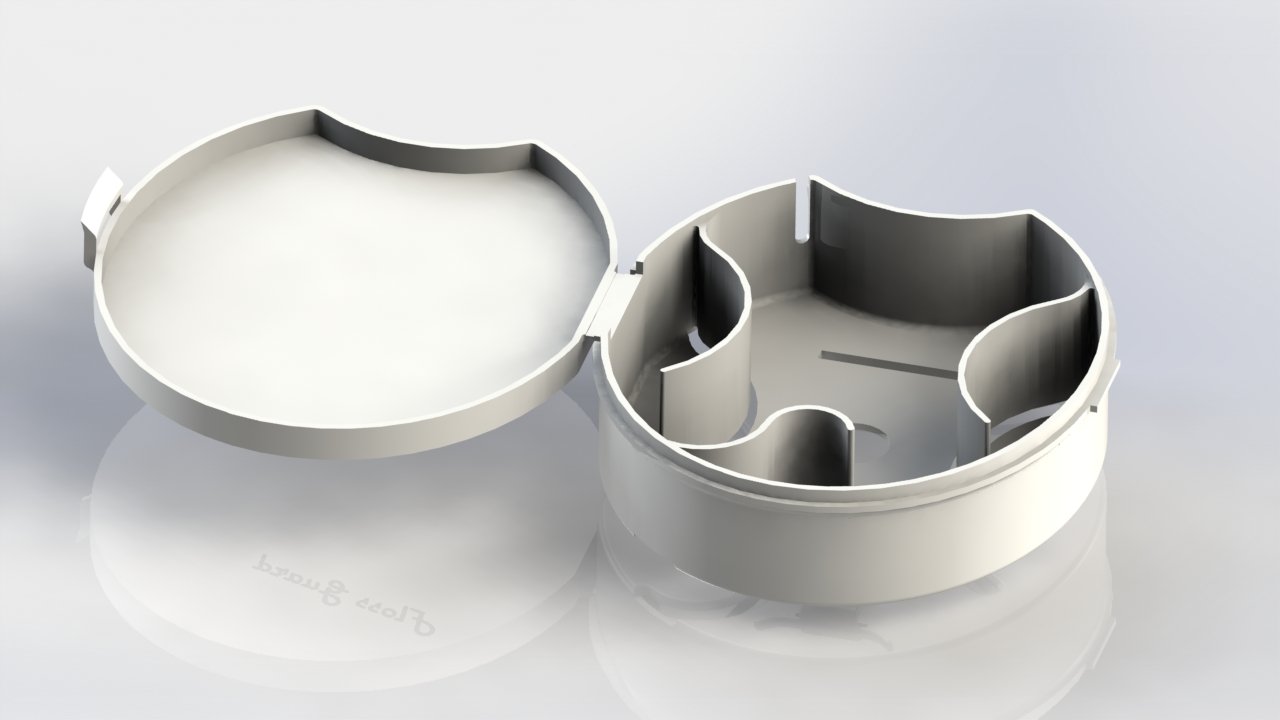
For instance, take a look at an old-style candy container, like an Altoids tin. Even on a cheap container like this, the tin is carefully folded around to make a hinge, creating a small, high-friction joint. Now, take a look at a Bubble Yum container (man, haven’t thought about these for a while) or a floss box, and notice the complete lack of sliding parts: a living hinge across the back has replaced friction with flexure.
Similarly, latches on old cabinets or enclosures used to be complex and friction prone: An axle support, pin, latch and spring were all part of the design. Current designs replace all this complexity with simple cantilever latches, eliminating not just a friction point but also a great deal of cost and complexity.
Of course, with any design, you can’t really trust it until you’ve tried a prototype, and luckily these days there are some great, cost-effective ways to test your designs.
Material Selection for Low Friction Prototypes
Happily, for most bushings—whether plastic or metal—and bearings, standard parts are available off the shelf, and can be inserted into your CNC machined or 3D-printed prototypes, testing real geometry and materials in full. Few reasons exist for customizing bearings and bushings, so take advantage of the inexpensive mass production.
For designs in which you’re looking at flexible plastics for your final design, prototyping becomes more complex. Many 3D printed materials are brittle, unable to withstand repeated flexure, so you’ll need to choose both the material and the printing method wisely.
In basic, low-cycle tests, PLA and TPU printed with FDM can be used to create good-quality living hinges. SLS in Nylon is another good choice for repeated flexure, while most PolyJet materials are known for being too brittle for many cycles—however, keep checking back on new PolyJet materials, because new materials are being produced all the time, and some of the more modern materials, like TangoPlus, have very good results with flexible applications. (For the latest on 3D Printing materials, check the Materials Guide, or sign up for updates here.)
Applications in Your Design
Whatever material and geometry you choose for your design, keeping in mind the basics of dynamic designs, looking at degrees of freedom, and examining ways to lower friction will always help the designs improve. We’ve come along way from beef tallow on wagon axles, but perhaps more surprising is that the basics haven’t changed since that era. One of the beautiful parts of mechanical design is the constants, the ways in which we can echo the designs from centuries past, and learn from the careful selection of materials, applying old principles to new designs. Want to learn more about choosing materials for your design? Check out our guide to material data sheets to learn what’s best for your design. And if you want to learn more about engineering and design, be sure to sign up to have our tips delivered right to your inbox!